 如何設置Arduino霍爾效應傳感器
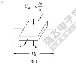
在本指南中,您將學習如何設置Arduino霍爾效應傳感器,特別是US1881,以檢測磁場。這對于需要查找電機的轉速或機器中其他運動的項目非常有用。
所需零件
Arduino的UNO
US1881霍爾效應傳感器
10kΩ電阻
4.7nF電容
面包板和跳線
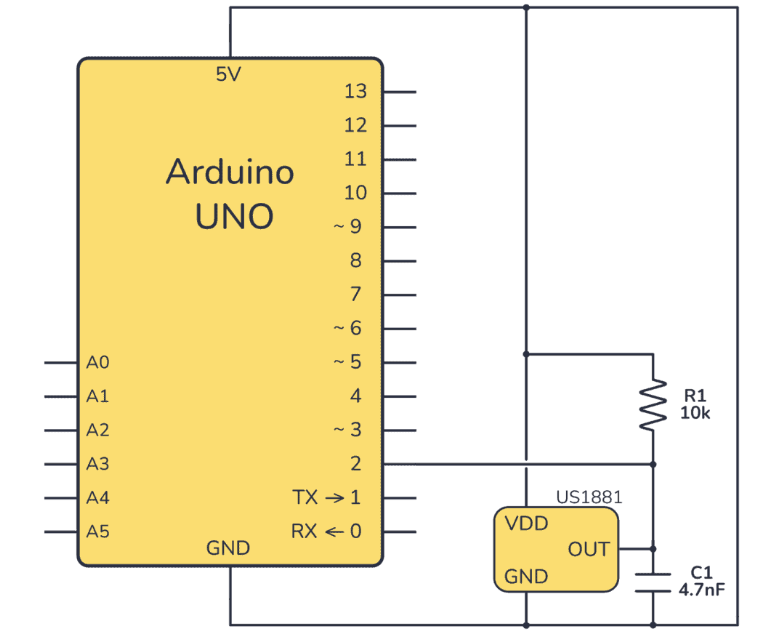
原理圖
將US1881霍爾效應傳感器的VDD引腳連接到Arduino上的5V,將GND引腳連接到GND。
該傳感器使用漏極開路輸出,這意味著您需要一個上拉電阻至5V,以便從中讀取任何值。電阻器的值并不重要。1k到100k就可以正常工作了。
輸出兩端的電容可穩定輸出,但可以跳過。
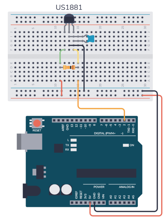
下面是如何將此電路連接到試驗板的示例:
Arduino霍爾效應傳感器測試代碼
要測試霍爾效應傳感器,您需要讀取輸出引腳,該引腳連接到Arduino數字引腳2。所以基本上你只需要代碼級地讀出值hallSensorState=digitalRead(D2);
下面是用于測試傳感器的完整代碼:
const int hallSensorPin = 2;  // Hall Effect sensor connected to digital pin 2
int hallSensorState;          // Variable to store the state of the sensor

void setup() {
  Serial.begin(9600);                // Start serial communication at 9600 baud
  pinMode(hallSensorPin, INPUT);     // Set the Hall Effect sensor pin as an INPUT
}

void loop() {
  hallSensorState = digitalRead(hallSensorPin); // Read the state of the sensor

  // Check if the sensor is detecting a magnetic field
  if (hallSensorState == HIGH) {
    Serial.println("Magnetic field detected!"); // If yes, print this message
  } else {
    Serial.println("No magnetic field detected."); // If no, print this message
  }

  delay(1000); // Wait for 1 second before the next read
}
分步說明
如上面的試驗板布局和原理圖所示組裝電路。
使用USB數據線將Arduino連接到您的計算機。
打開ArduinoIDE并將示例代碼復制到新草圖中。
將草圖上傳到Arduino板。
打開串行監視器以查看輸出消息。當磁鐵靠近傳感器時,您應該會看到“檢測到磁場!”,如果沒有,您應該會看到“未檢測到磁場”。
確保所有連接都是安全的,并與原理圖相匹配。
如果傳感器始終顯示“HIGH”,請檢查附近是否有任何磁源,包括面包板電源軌內的磁鐵。
如果傳感器未檢測到磁場,請確保磁鐵離傳感器足夠近。
結論
現在您知道如何在Arduino中使用霍爾效應傳感器檢測磁場。此設置可用作磁性門傳感器,用于RPM計數,或用于任何需要磁場檢測的項目。
審核編輯:陳陳
聲明:本文內容及配圖由入駐作者撰寫或者入駐合作網站授權轉載。文章觀點僅代表作者本人,不代表電子發燒友網立場。文章及其配圖僅供工程師學習之用,如有內容侵權或者其他違規問題,請聯系本站處理。
舉報投訴
-
Arduino
+關注
關注
188文章
6477瀏覽量
187813 -
霍爾效應傳感器
+關注
關注
1文章
249瀏覽量
15628
發布評論請先 登錄
相關推薦
霍爾效應傳感器設計的技巧
作為汽車產業的一個組成部分,霍爾效應傳感器用于在諸如底盤、安全、車身、保障及動力傳動等極其廣泛的一系列應用中檢測端位置或測量線性或角運動。目前,主導汽車行業研發討論的一個重要話題是功能安全。功能安全影響到所有應用系統組件的設
發表于 06-10 15:44
?6970次閱讀

使用霍爾效應傳感器檢測磁鐵的存在并制作速度計,防盜報警器等等!
您是否曾經想要制作一個涉及非接觸式傳感的項目,例如,檢測車門關閉,計算車輪轉數或制作車速表?那么這款Arduino霍爾效應傳感器教程就是為您
發表于 12-04 15:35
怎樣使用霍爾效應傳感器和Arduino控制繼電器
如果您還記得我們之前實施的 Arduino WaterFlow傳感器教程,水流傳感器的主要組件是霍爾效應IC 。
基于霍爾效應傳感器的Fidget Spinner RPM轉速計
大家好!這是我的下一個項目,Fidget Spinner RPM Counter 或帶有霍爾效應傳感器的 Arduino 轉速計。一:要求所需零件:指尖陀螺釹磁鐵
發表于 12-21 12:34
?2次下載


 工商網監
工商網監
評論