") 構(gòu)建一個帶Arduino代碼的顏色檢測器電路
構(gòu)建一個帶Arduino代碼的顏色檢測器電路
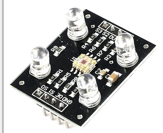
在這篇文章中,我們將構(gòu)建一個可以檢測顏色并觸發(fā)相應分配繼電器的電路。該項目是使用 TCS3200 顏色傳感器和 Arduino 板完成的。
通過 TCS3200 進行顏色感應
如果您希望電路根據(jù)顏色采取行動,則建議的項目可能會很有用。在各種工業(yè)領域,基于顏色檢測的應用海量很大。
該項目將深入了解我們?nèi)绾螌︻伾珎鞲衅鬟M行編程以檢測不同的顏色并觸發(fā)繼電器。
我們將考慮該項目的原色:紅色、綠色和藍色。該項目可以區(qū)分這三種顏色并觸發(fā)繼電器,每個繼電器代表每種顏色。
TCS3200 可以檢測任意數(shù)量的顏色,但為了使項目易于理解并保持程序代碼簡單,我們只關(guān)注原色。
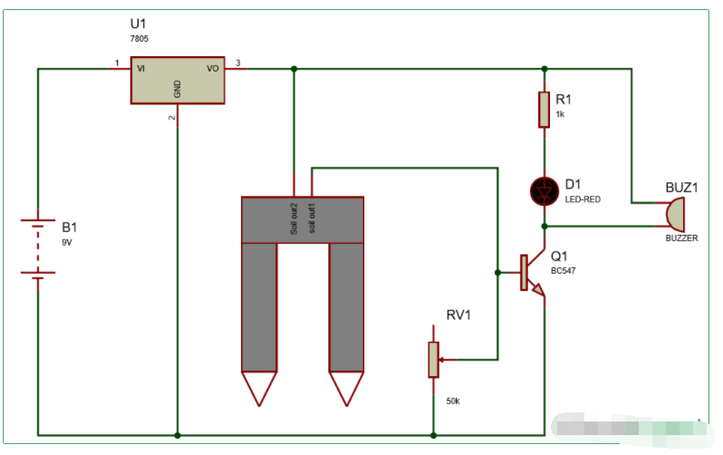
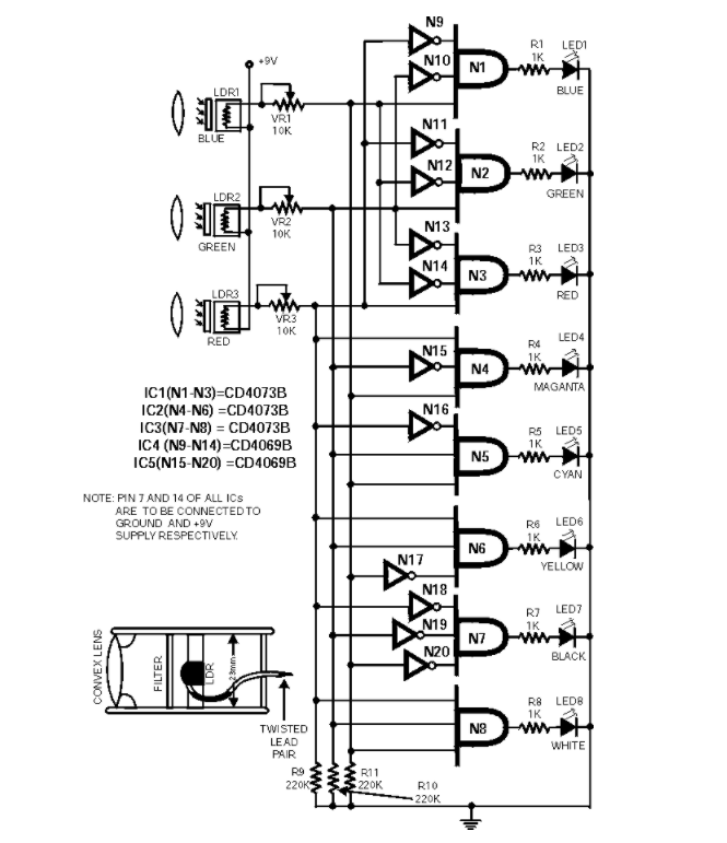
電路圖:
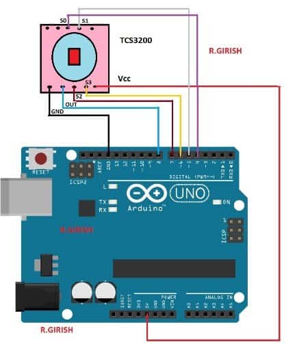
以上原理圖用于連接Arduino和TCS3200顏色傳感器。
繼電器連接:
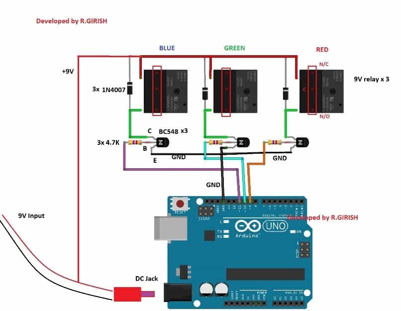
使用至少 9mA 的 500V 適配器為 Arduino
供電。晶體管充當繼電器的放大器,因為Arduino的GPIO引腳不能提供足夠的電流來繼電器。
二極管 1N4007 將吸收繼電器線圈的高壓尖峰,保護其余半導體元件。
硬件到此結(jié)束。
現(xiàn)在讓我們看看如何上傳代碼并根據(jù)您的要求校準傳感器。
顏色靈敏度可能因模塊而異,環(huán)境光會極大地改變顏色靈敏度。
所有TCS3200傳感器在制造時都有一些變化,您必須測量當前擁有的傳感器的顏色參數(shù),以便可以在代碼中使用這些參數(shù)來更準確地檢測顏色。
要校準和優(yōu)化傳感器的讀數(shù),請精確執(zhí)行以下步驟:
步驟 1:上傳以下代碼并完成硬件設置。
//--------Program Developed by R.GIRISH-------//
const int s0 = 4;
const int s1 = 5;
const int s2 = 6;
const int s3 = 7;
const int out = 8;
int frequency1 = 0;
int frequency2 = 0;
int frequency3 = 0;
int state = LOW;
int state1 = LOW;
int state2 = HIGH;
void setup()
{
Serial.begin(9600);
pinMode(s0, OUTPUT);
pinMode(s1, OUTPUT);
pinMode(s2, OUTPUT);
pinMode(s3, OUTPUT);
pinMode(out, INPUT);
//----Scaling Frequency 20%-----//
digitalWrite(s0, state2);
digitalWrite(s1, state1);
//-----------------------------//
}
void loop()
{
//-----Sensing RED colour-----//
digitalWrite(s2, state1);
digitalWrite(s3, state1);
frequency1 = pulseIn(out, state);
Serial.print(“RED = ”);
Serial.print(frequency1);
Serial.print(“ |”);
delay(100);
//------Sensing Green colour----//
digitalWrite(s2, state2);
digitalWrite(s3, state2);
frequency2 = pulseIn(out, state);
Serial.print(“ Green = ”);
Serial.print(frequency2);
Serial.print(“ |”);
delay(100);
//------Sensing Blue colour----//
digitalWrite(s2, state1);
digitalWrite(s3, state2);
frequency3 = pulseIn(out, state);
Serial.print(“ Blue = ”);
Serial.println(frequency3);
delay(100);
Serial.println(“-----------------------------”);
delay(400);
}
//---------Program Developed by R.GIRISH---------//
Step 2: Open the serial monitor, you will find the color parameters like
this:
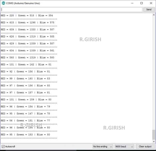
Bring the color object (colored paper is preferred) red, blue and
green.
Step 3:
? Place the red colored paper close to the TCS3200 sensor.
? Note down the R, G, B readings (all three colours) while you place the
red colour paper.
? Similarly note down the R, G, B reading for green and blue color
papers.
? NOTE: when you place any of the 3 colors in front of the TCS3200 note
down all the red, blue and green readings for each color paper, which you need
to enter in the main color detection program.
Step 4: Read Step 5 and upload the main below code (color detection
program)
//-----Program Developed by R.GIRISH-----//
const int Red_relay = 9;
const int Green_relay = 10;
const int Blue_relay = 11;
const int s0 = 4;
const int s1 = 5;
const int s2 = 6;
const int s3 = 7;
const int out = 8;
int var = 25;
int red = 0;
int green = 0;
int blue = 0;
int state = LOW;
int state1 = LOW;
int state2 = HIGH;
//-----------Enter Values--------//
//For RED Colour:
int Rx1 = 92;
int Gx1 = 240;
int Bx1 = 53;
//For GREEN Colour:
int Rx2 = 228;
int Gx2 = 163;
int Bx2 = 64;
//For BLUE Colour:
int Rx3 = 300;
int Gx3 = 144;
int Bx3 = 45;
//----------------------------//
void setup()
{
Serial.begin(9600);
pinMode(Red_relay, OUTPUT);
pinMode(Green_relay, OUTPUT);
pinMode(Blue_relay, OUTPUT);
digitalWrite(Red_relay, LOW);
digitalWrite(Green_relay, LOW);
digitalWrite(Blue_relay, LOW);
pinMode(s0, OUTPUT);
pinMode(s1, OUTPUT);
pinMode(s2, OUTPUT);
pinMode(s3, OUTPUT);
pinMode(out, INPUT);
//----Scaling Frequency 20%-----//
digitalWrite(s0, state2);
digitalWrite(s1, state1);
//-----------------------------//
}
void loop()
{
int redH1 = Rx1 + var;
int redL1 = Rx1 - var;
int redH2 = Rx2 + var;
int redL2 = Rx2 - var;
int redH3 = Rx3 + var;
int redL3 = Rx3 - var;
int blueH1 = Bx1 + var;
int blueL1 = Bx1 - var;
int blueH2 = Bx2 + var;
int blueL2 = Bx2 - var;
int blueH3 = Bx3 + var;
int blueL3 = Bx3 - var;
int greenH1 = Gx1 + var;
int greenL1 = Gx1 - var;
int greenH2 = Gx2 + var;
int greenL2 = Gx2 - var;
int greenH3 = Gx3 + var;
int greenL3 = Gx3 - var;
//-----Sensing RED colour-----//
digitalWrite(s2, state1);
digitalWrite(s3, state1);
red = pulseIn(out, state);
delay(100);
//------Sensing Green colour----//
digitalWrite(s2, state2);
digitalWrite(s3, state2);
green = pulseIn(out, state); ;
delay(100);
//------Sensing Blue colour----//
digitalWrite(s2, state1);
digitalWrite(s3, state2);
blue = pulseIn(out, state);
delay(400);
if(red 《= redH1 && red 》= redL1)
{
if(green 《= greenH1 && green 》= greenL1)
{
if(blue 《= blueH1 && blue 》= blueL1)
{
Serial.println(“Detected Colour: RED”);
Serial.println(“”);
digitalWrite(Red_relay, HIGH);
delay(1000);
}
}
}
if(red 《= redH2 && red 》= redL2)
{
if(green 《= greenH2 && green 》= greenL2)
{
if(blue 《= blueH2 && blue 》= blueL2)
{
Serial.println(“Detected Colour: Green”);
Serial.println(“”);
digitalWrite(Green_relay, HIGH);
delay(1000);
}
}
}
if(red 《= redH3 && red 》= redL3)
{
if(green 《= greenH3 && green 》= greenL3)
{
if(blue 《= blueH3 && blue 》= blueL3)
{
Serial.println(“Detected Colour: Blue”);
Serial.println(“”);
digitalWrite(Blue_relay, HIGH);
delay(1000);
}
}
}
}
//------Program Developed by R.GIRISH--------//
第 5 步: 在上面的代碼中,將值替換為您最近記下的值:
//-- -- -- -- Enter Values-- -- --//
//For RED Colour:
int Rx1 = 92;
int Gx1 = 240;
int Bx1 = 53;
//For GREEN Colour:
int Rx2 = 228;
int Gx2 = 163;
int Bx2 = 64;
//For BLUE Colour:
int Rx3 = 300;
int Gx3 = 144;
int Bx3 = 45;
//-- -- -- -- -- -- -- -- -- -- -- //
當您將紅色紙放在傳感器上時,您將獲得三個讀數(shù),例如R = 56 |G = 78 |B = 38。
按如下所示放置值 56、78、38:
對于紅色:
int Rx1 = 56;
int Gx1 = 78;
int Bx1 = 38;
同樣,對于其他兩種顏色并上傳代碼。
步驟6:
? 打開串行監(jiān)視器,將三種顏色中的任何一種放在傳感器前面。
?您將在串行監(jiān)視器上看到顏色檢測;同時激活相應的顏色繼電器。
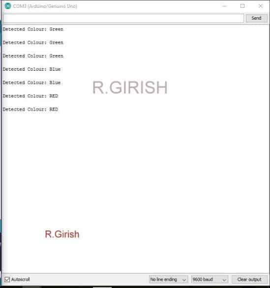
? 您有 Arduino 板上的重置按鈕來停用繼電器。
注1:校準后,如果您放置的紅色,綠色,藍色物體/紙張的陰影/色調(diào)略有不同,則電路可能無法檢測到顏色。換句話說,您必須使用完全相同顏色的物體/紙張來檢測顏色并觸發(fā)中繼。
注2:環(huán)境光會影響顏色檢測,因此,在校準和檢測顏色時,請在傳感器附近保持一致的光線。
-
檢測電路
+關(guān)注
關(guān)注
13文章
308瀏覽量
58268 -
檢測器
+關(guān)注
關(guān)注
1文章
869瀏覽量
47787 -
Arduino
+關(guān)注
關(guān)注
188文章
6477瀏覽量
187834
發(fā)布評論請先 登錄
相關(guān)推薦
構(gòu)建一個基于晶體管的簡單土壤濕度檢測器電路
構(gòu)建一個簡單的空氣流量檢測器電路
基于物聯(lián)網(wǎng)的LPG氣體泄漏檢測器
采用Arduino開發(fā)板、火焰?zhèn)鞲?b class='flag-5'>器和蜂鳴器構(gòu)建火感檢測器系統(tǒng)
使用霍爾傳感器和LED構(gòu)建一個磁極性檢測器
構(gòu)建一個基于Arduino的貨幣計數(shù)器
使用二極管和電容器構(gòu)建簡單的峰值檢測器電路
Arduino Light Clapper使用聲音檢測器

使用TCS230 TCS3200顏色傳感器制作顏色檢測器
使用Arduino和雨滴傳感器的雨量檢測器


 工商網(wǎng)監(jiān)
評論