") 如何使用PIC16F877A和ACS712-5A制作數(shù)字電流表
如何使用PIC16F877A和ACS712-5A制作數(shù)字電流表
在制作或調(diào)試任何電氣系統(tǒng)時(shí),測(cè)量電壓和電流總是有幫助的。在這個(gè)項(xiàng)目中,我們將 使用PIC16F877A微控制器和電流傳感器ACS712-5A制作自己的數(shù)字電流表 。該項(xiàng)目可以測(cè)量0-30A范圍內(nèi)的交流和直流電流,精度為0.3A。只需對(duì)代碼進(jìn)行少量修改,您也可以使用此電路測(cè)量高達(dá)30A的電流。
所需材料:
ACS712電流傳感器的工作原理:
在我們開(kāi)始構(gòu)建項(xiàng)目之前,了解 ACS712 電流傳感器的工作原理對(duì)我們來(lái)說(shuō)非常重要,因?yàn)樗琼?xiàng)目的關(guān)鍵組件。測(cè)量電流,尤其是交流電流始終是一項(xiàng)艱巨的任務(wù),因?yàn)樵肼暭由喜徽_的隔離問(wèn)題等。但是,借助由Allegro設(shè)計(jì)的ACS712模塊,事情變得容易多了。
該模塊的工作原理是霍爾效應(yīng),這是由埃德溫·霍爾博士發(fā)現(xiàn)的。根據(jù)他的原理,當(dāng)載流導(dǎo)體被放入磁場(chǎng)中時(shí),在其邊緣垂直于電流和磁場(chǎng)方向產(chǎn)生電壓。讓我們不要太深入這個(gè)概念,簡(jiǎn)單地說(shuō),我們使用霍爾傳感器來(lái)測(cè)量載流導(dǎo)體周圍的磁場(chǎng)。該測(cè)量將以毫伏為單位,我們稱之為霍爾電壓。該測(cè)量的霍爾電壓與流過(guò)導(dǎo)體的電流成正比。
使用 ACS712 電流傳感器的主要優(yōu)點(diǎn)是可以測(cè)量交流和直流電流,它還在負(fù)載(交流/直流負(fù)載)和測(cè)量單元(微控制器部分)之間提供隔離。如圖所示,模塊上有三個(gè)引腳,分別是Vcc,Vout和接地。

2 針接線端子是載流線應(yīng)穿過(guò)的位置。模塊工作在+5V,因此Vcc應(yīng)由5V供電,接地應(yīng)連接到系統(tǒng)的地。Vout引腳的失調(diào)電壓為2500mV,這意味著當(dāng)沒(méi)有電流流過(guò)導(dǎo)線時(shí),輸出電壓將為2500mV,當(dāng)電流為正時(shí),電壓將大于2500mV,當(dāng)電流為負(fù)時(shí),電壓將小于2500mV。
我們將使用 PIC 微控制器的 ADC 模塊來(lái)讀取模塊的輸出電壓 (Vout),當(dāng)沒(méi)有電流流過(guò)導(dǎo)線時(shí),輸出電壓為 512(2500mV)。當(dāng)電流以負(fù)方向流動(dòng)時(shí),該值將減小,當(dāng)電流沿正方向流動(dòng)時(shí),該值將增加。下表將幫助您了解輸出電壓和ADC值如何根據(jù)流過(guò)導(dǎo)線的電流而變化。
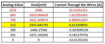
這些值是根據(jù) ACS712 數(shù)據(jù)表中給出的信息計(jì)算得出的。您也可以使用以下公式計(jì)算它們:
Vout Voltage(mV) = (ADC Value/  1023)*5000
Current Through the Wire (A) = (Vout(mv)-2500)/185
現(xiàn)在,我們知道了ACS712傳感器的工作原理以及我們可以從中得到什么。讓我們繼續(xù)看電路圖。
電路圖:
下圖顯示了該數(shù)字電流表項(xiàng)目的完整電路圖。
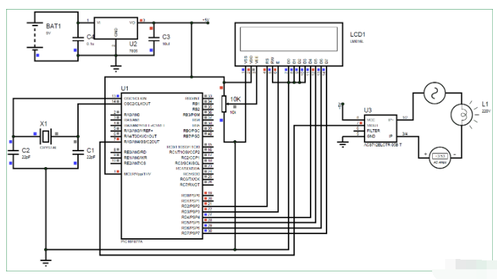
完整的數(shù)字電流計(jì)電路工作在+5V電壓下,由7805穩(wěn)壓器調(diào)節(jié)。我們使用 16X2 LCD 來(lái)顯示電流值。電流傳感器 (Vout) 的輸出引腳連接到 7^千^PIC的引腳,即AN4,用于讀取模擬電壓。
此外,PIC 的引腳連接如下表所示
| S.No: | 引腳編號(hào) | 引腳名稱 | 已連接到 |
|---|---|---|---|
| 1 | 21 | RD2 | 液晶顯示器的 RS |
| 2 | 22 | RD3 | 液晶顯示器的E |
| 3 | 27 | RD4 | 液晶屏D4 |
| 4 | 28 | RD5 | 液晶屏D5 |
| 5 | 29 | RD6 | 液晶屏D6 |
| 6 | 30 | RD7 | 液晶屏D7 |
| 7 | 7 | AN4 | 當(dāng)前塞斯諾的沃特 |
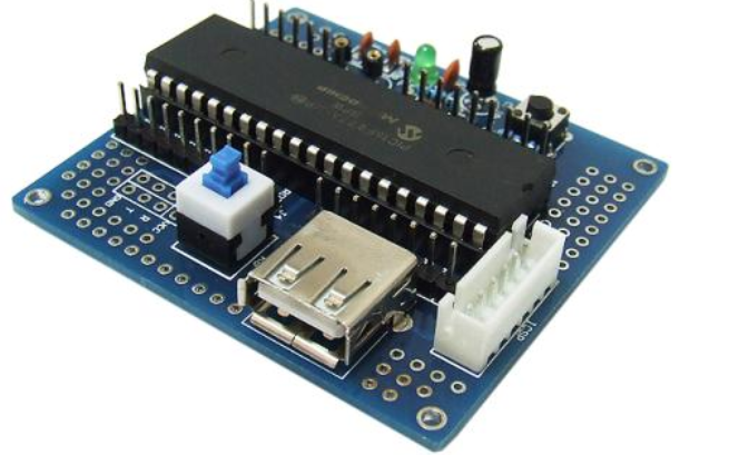
您可以在面包板上構(gòu)建此數(shù)字電流表電路或使用性能板。如果您一直遵循PIC教程,那么您還可以重用我們用于學(xué)習(xí)PIC微控制器的硬件。在這里,我們使用了與PIC微控制器一起為L(zhǎng)ED閃爍構(gòu)建的相同 性能板 ,如下所示:
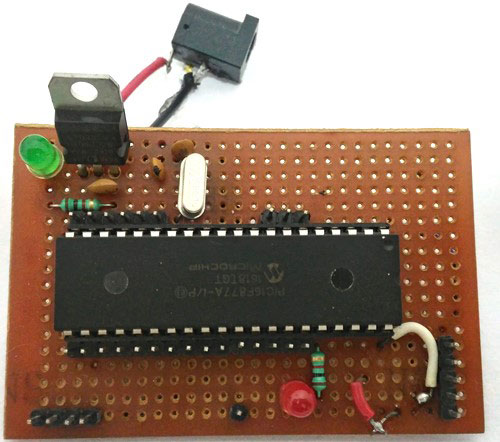
注意: 構(gòu)建此板不是強(qiáng)制性的,您可以簡(jiǎn)單地按照電路圖在面包板上構(gòu)建電路,并使用任何轉(zhuǎn)儲(chǔ)器套件將程序轉(zhuǎn)儲(chǔ)到 PIC 微控制器中。
模擬:
在您實(shí)際使用硬件之前,也可以使用 Proteus 模擬此 電流表電路 。分配本教程末尾給出的代碼的十六進(jìn)制文件,然后單擊播放按鈕。您應(yīng)該能夠注意到LCD顯示屏上的電流。我使用燈作為交流負(fù)載,您可以通過(guò)單擊它來(lái)改變燈的內(nèi)阻以改變流過(guò)它的電流。
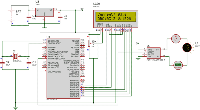
如上圖所示,電流表顯示流過(guò)燈的實(shí)際電流約為 3.52 A,LCD 顯示電流約為 3.6 A。但是,在實(shí)際情況下, 我們可能會(huì)得到高達(dá)0.2A的誤差 。ADC值和電壓(mV)也顯示在LCD上,供您理解。
PIC微控制器編程:
如前所述,完整的代碼可以在本文末尾找到。該代碼是用注釋行自我解釋的,只涉及將LCD與PIC微控制器連接的概念,以及在PIC微控制器中使用ADC模塊的概念,我們已經(jīng)在之前的PIC微控制器學(xué)習(xí)教程中介紹過(guò)。
從傳感器讀取的值將不準(zhǔn)確,因?yàn)殡娏魇墙涣鞯牟⑶疫€受到噪聲的影響。因此,我們讀取ADC值20次并將其平均以獲得適當(dāng)?shù)碾娏髦担缦旅娴拇a所示。
我們使用上面解釋的相同公式來(lái)計(jì)算電壓和電流值。
for (int i=0; i<20;i++) //Read value for 20 Times
        {
        adc=0;
        adc=ADC_Read(4); //Read ADC
        Voltage = adc*4.8828; //Calculate the Voltage

        if (Voltage>=2500) //If the current is positive
              Amps += ((Voltage-2500)/18.5);

        else if (Voltage<=2500) //If the current is negative
              Amps += ((2500-Voltage)/18.5);
        }

        Amps/=20;  //Average the value that was read for 20 times
由于該項(xiàng)目也可以讀取交流電流,因此電流也將是負(fù)的和正的。也就是說(shuō),輸出電壓值將高于和低于2500mV。因此,如下圖所示,我們更改了負(fù)電流和正電流的公式,以便我們不會(huì)得到負(fù)值。
if (Voltage>=2500) //If the current is positive
              Amps += ((Voltage-2500)/18.5);

        else if (Voltage<=2500) //If the current is negative
              Amps += ((2500-Voltage)/18.5);
使用 30A 電流傳感器:
如果您需要測(cè)量超過(guò) 5A 的電流,您可以簡(jiǎn)單地購(gòu)買 ACS712-30A 模塊并以相同的方式連接它,并通過(guò)將 18.5 替換為 0.66 來(lái)更改以下代碼行,如下所示:
if (Voltage>=2500) //If the current is positive
              Amps += ((Voltage-2500)/0.66);

        else if (Voltage<=2500) //If the current is negative
              Amps += ((2500-Voltage)/0.66);
如果要測(cè)量低電流,還可以使用AVR微控制器檢查100mA電流表。
加工:
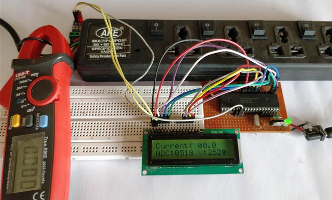
一旦您對(duì)PIC微控制器進(jìn)行了編程并準(zhǔn)備好了硬件。只需打開(kāi)負(fù)載和PIC微控制器的電源,您應(yīng)該能夠看到電流通過(guò)LCD屏幕上顯示的電線。
注意: 如果您使用的是 ASC7125A 模塊,請(qǐng)確保您的負(fù)載消耗不超過(guò) 5A,同時(shí)使用更高規(guī)格的導(dǎo)線作為載流導(dǎo)體。
/*
Digital Ammeter for PIC16F877A
* Code by: B.Aswinth Raj
* Dated: 27-07-2017
* More details at: www.CircuitDigest.com
*/
#define _XTAL_FREQ 20000000
#define RS RD2
#define EN RD3
#define D4 RD4
#define D5 RD5
#define D6 RD6
#define D7 RD7
#include -
微控制器
+關(guān)注
關(guān)注
48文章
7651瀏覽量
152124 -
PIC16F877A
+關(guān)注
關(guān)注
2文章
43瀏覽量
21864 -
電流傳感器
+關(guān)注
關(guān)注
10文章
1029瀏覽量
41283 -
數(shù)字電流表
+關(guān)注
關(guān)注
0文章
6瀏覽量
7481
發(fā)布評(píng)論請(qǐng)先 登錄
相關(guān)推薦
PIC16F877A在proteus中讀寫(xiě)AT24C512
PIC16F877A串口發(fā)送查詢方式
PIC16F877A串口芯片電壓?jiǎn)栴}
PIC16F877A的UART通信和proteus仿真的資料合集免費(fèi)下載
PIC16F877A的T0定時(shí)器制作的電子鐘程序
PIC16F877A開(kāi)發(fā)板 數(shù)碼管動(dòng)態(tài)掃描實(shí)驗(yàn)

PIC16F877A開(kāi)發(fā)板 普通IO驅(qū)動(dòng)74595實(shí)驗(yàn)
PIC16F877A 看門狗定時(shí)器實(shí)驗(yàn)
用PIC16F877A和TB6612FNG電機(jī)驅(qū)動(dòng)的微型電路
使用熱敏打印機(jī)連接PIC16F877A并使用輕觸開(kāi)關(guān)實(shí)現(xiàn)打印的教程
PIC16F877A單片機(jī)代碼生成系統(tǒng)
基于PIC16F877A的4位密碼電子鎖的制作


 工商網(wǎng)監(jiān)
評(píng)論