") 使用Wii nunchuk手柄連接Arduino控制伺服電機的方法
使用Wii nunchuk手柄連接Arduino控制伺服電機的方法
簡介
偶然在箱子里發(fā)現(xiàn)一個舊的Wii Nunchuk手柄,又叫“雙節(jié)棍”手柄,我想它是否可以用來控制Arduino,查閱了相關資料,確定Nunchuk手柄支持I2C方式連接到Arduino, 通過不斷地研究深入,最后從todbot.com等網(wǎng)站上找到了相關的控制Will nunchuk的代碼,于是就將代碼移植過來,實現(xiàn)了 Will nunchuk 對伺服電機的控制!
Wii Nunchuk接口定義
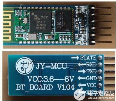
把Wii Nunchuk和Arduino連接起來有幾種方法,我們可以買一個Wii nunchuk的適配器,或者像剪斷連接線,確保手柄再不需要和Wii連接使用了。本文采用了剪斷線的方法,剪線之后再焊接了插針到nunchuk的連線,這樣就可以和面包板更好的連接了。下圖是Wii Nunchuk的接口定義 。
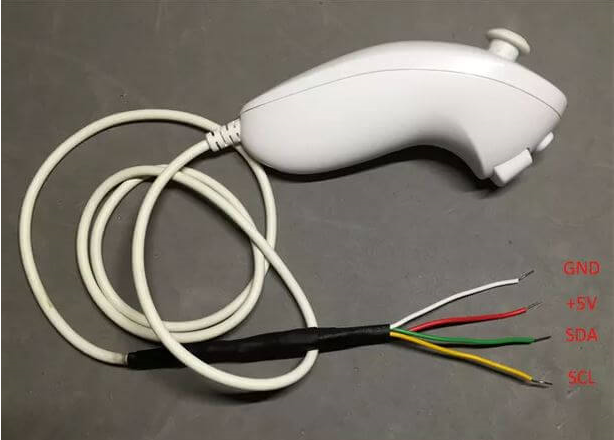
Wii Nunchuk手柄接口定義
Wii Nunchuk連接Arduino
手柄白線 (GND) –》 Arduino GND
手柄紅線 ( +5V ) –》 Arduino 5V
手柄綠線 (SDA) –》 模擬引腳 4 或者 專用的 SDA pin
手柄黃線 (SCL) –》 模擬引腳 5 或者 專用的 SCL pin
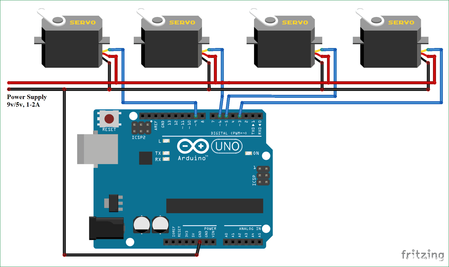
連接伺服電機到Arduino
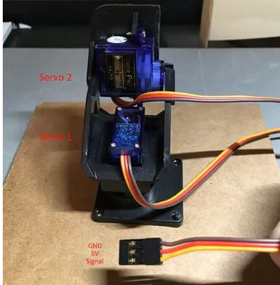
雙軸舵機云臺
Servo 1 (x-axis)
舵機棕線 (GND) –》 Arduino GND
舵機紅線 (5V) –》 Arduino 5V
舵機黃線 (data/Signal) –》 Arduino Pin 10
Servo 2 (y-axis)
舵機棕線 (GND) –》 Arduino GND
舵機紅線 (5V) –》 Arduino 5V
舵機黃線 (data/Signal) –》 Arduino Pin 9
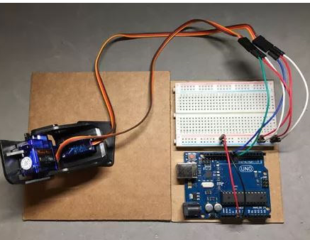
舵機云臺連接Arduino UNO
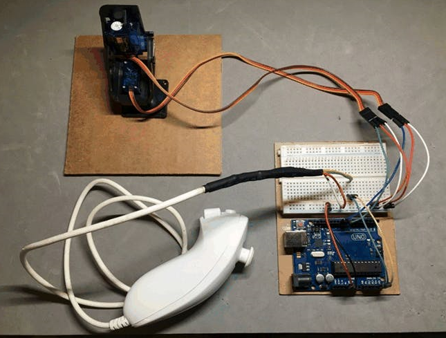
連接全部組件
代碼部分
使用Arduino IDE上傳代碼前,需要兩個標準庫: Wire.h 、 Servo.h 。
代碼的執(zhí)行順序如下:
初始化Nunchuk手柄的I2C接口;
初始化伺服系統(tǒng) ;
讀取Nunchuk手柄的數(shù)據(jù);
根據(jù)讀取得 Nunchuk 手柄的實時數(shù)據(jù)控制伺服電機運動。
完整代碼如下:
/*
* NunchuckPrint
* 2007 Tod E. Kurt, http://todbot.com/blog/
* Change log:
*
* Mark Tashiro - Changed Wire.read to Wire.write
* Changed Wire.receive to Wire.read
* Added code for servos
*/
#include
#include
Servo servoLeft; // Define left servo
Servo servoRight; // Define right servo
static uint8_t nunchuck_buf[6]; // array to store nunchuck data,
void setup()
{
Serial.begin(19200);
servoLeft.attach(10); // Set left servo to digital pin 10
servoRight.attach(9); // Set right servo to digital pin 9
nunchuck_setpowerpins(); // use analog pins 2&3 as fake gnd & pwr
nunchuck_init(); // send the initilization handshake
Serial.print ("Finished setup\n");
}
void loop()
{
nunchuck_get_data();
// map nunchuk data to a servo data point
int x_axis = map(nunchuck_buf[0], 23, 222, 180, 0);
int y_axis = map(nunchuck_buf[1], 32, 231, 0, 180);
//move servo to desired position based on Wii nunchuk reading
servoLeft.write(x_axis);
servoRight.write(y_axis);
// un-comment next line to print data to serial monitor
// nunchuck_print_data();
}
//
// Nunchuck functions
//
// Uses port C (analog in) pins as power & ground for Nunchuck
static void nunchuck_setpowerpins()
{
#define pwrpin PORTC3
#define gndpin PORTC2
DDRC |= _BV(pwrpin) | _BV(gndpin);
PORTC &=~ _BV(gndpin);
PORTC |= _BV(pwrpin);
delay(100); // wait for things to stabilize
}
// initialize the I2C system, join the I2C bus,
// and tell the nunchuck we're talking to it
void nunchuck_init()
{
Wire.begin(); // join i2c bus as master
Wire.beginTransmission(0x52); // transmit to device 0x52
Wire.write(0x40); // sends memory address
Wire.write(0x00); // sends sent a zero.
Wire.endTransmission(); // stop transmitting
}
// Send a request for data to the nunchuck
// was "send_zero()"
void nunchuck_send_request()
{
Wire.beginTransmission(0x52); // transmit to device 0x52
Wire.write(0x00); // sends one byte
Wire.endTransmission(); // stop transmitting
}
// Receive data back from the nunchuck,
int nunchuck_get_data()
{
int cnt=0;
Wire.requestFrom (0x52, 6); // request data from nunchuck
while (Wire.available ()) {
// receive byte as an integer
nunchuck_buf[cnt] = nunchuk_decode_byte(Wire.read());
cnt++;
}
nunchuck_send_request(); // send request for next data payload
// If we recieved the 6 bytes, then go print them
if (cnt >= 5) {
return 1; // success
}
return 0; //failure
}
// Print the input data we have recieved
// accel data is 10 bits long
// so we read 8 bits, then we have to add
// on the last 2 bits. That is why I
// multiply them by 2 * 2
void nunchuck_print_data()
{
static int i=0;
int joy_x_axis = nunchuck_buf[0];
int joy_y_axis = nunchuck_buf[1];
int accel_x_axis = nunchuck_buf[2]; // * 2 * 2;
int accel_y_axis = nunchuck_buf[3]; // * 2 * 2;
int accel_z_axis = nunchuck_buf[4]; // * 2 * 2;
int z_button = 0;
int c_button = 0;
// byte nunchuck_buf[5] contains bits for z and c buttons
// it also contains the least significant bits for the accelerometer data
// so we have to check each bit of byte outbuf[5]
if ((nunchuck_buf[5] >> 0) & 1)
z_button = 1;
if ((nunchuck_buf[5] >> 1) & 1)
c_button = 1;
if ((nunchuck_buf[5] >> 2) & 1)
accel_x_axis += 2;
if ((nunchuck_buf[5] >> 3) & 1)
accel_x_axis += 1;
if ((nunchuck_buf[5] >> 4) & 1)
accel_y_axis += 2;
if ((nunchuck_buf[5] >> 5) & 1)
accel_y_axis += 1;
if ((nunchuck_buf[5] >> 6) & 1)
accel_z_axis += 2;
if ((nunchuck_buf[5] >> 7) & 1)
accel_z_axis += 1;
Serial.print(i,DEC);
Serial.print("\t");
Serial.print("joy:");
Serial.print(joy_x_axis,DEC);
Serial.print(",");
Serial.print(joy_y_axis, DEC);
Serial.print(" \t");
Serial.print("acc:");
Serial.print(accel_x_axis, DEC);
Serial.print(",");
Serial.print(accel_y_axis, DEC);
Serial.print(",");
Serial.print(accel_z_axis, DEC);
Serial.print("\t");
Serial.print("but:");
Serial.print(z_button, DEC);
Serial.print(",");
Serial.print(c_button, DEC);
Serial.print("\r\n"); // newline
i++;
}
// Encode data to format that most wiimote drivers except
// only needed if you use one of the regular wiimote drivers
char nunchuk_decode_byte (char x)
{
x = (x ^ 0x17) + 0x17;
return x;
}
-
伺服電機
+關注
關注
85文章
2057瀏覽量
58190 -
Arduino
+關注
關注
188文章
6477瀏覽量
187814
發(fā)布評論請先 登錄
相關推薦
如何使用Arduino的藍牙控制伺服電機
如何使用Arduino和ESP8266實現(xiàn)網(wǎng)頁控制伺服電機
如何使用Arduino開發(fā)板控制多臺伺服電機
如何使用Arduino開發(fā)板通過藍牙方式控制伺服電機
arduino連接ps2手柄控制智能小車實踐記錄
使用Arduino Uno和POT控制伺服電機

基于Arduino UNO的手勢控制伺服電機
Arduino/Android藍牙多伺服電機控制
用Arduino控制伺服電機的超級簡單方法
如何使用操縱桿和Arduino控制伺服電機
如何使用Arduino UNO板和電位器控制伺服電機


 工商網(wǎng)監(jiān)
評論