 基于STM32的元器件特性測試儀過程
元器件特性測試儀任務要求
通過編程完成對5種以上元器件特性的測量
能夠自動識別元器件
在OLED屏幕上通過圖形化的界面顯示各種元器件的符號及測量得到的信息
實驗環境
硬件:STM32G031G8U6核心板、硬禾學堂制作的底板
軟件:STM32CubeMX、CLion、STM32CubeProgrammer
實現思路
首先進行一個大致的元器件類型的判斷,再精確地測量元器件的各項屬性,最后顯示在OLED屏幕上
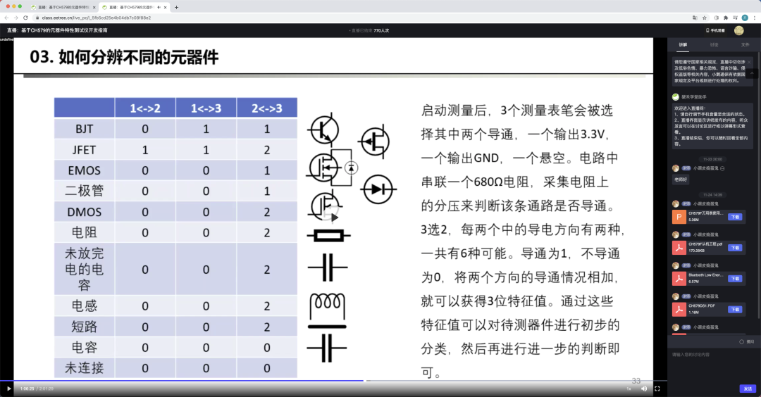
各部分的介紹元器件類型的判斷
思路:首先給元器件放電,再輪番給這3pin中的每2pin進行正反地通電,會得到六次結果。將每2pin的結果存儲下來,進行排序后根據元器件特性進行判斷元器件的類型,初步判斷后存下引腳信息并進行參數的測量和屏幕顯示,具體參考如圖:
代碼如下
void QuickCheck() {
QUICKJUDGE result = {0}; //before compare, the result.sat should be sorted
uint8_t BJTFEA[4] = “011”; //BJT
uint8_t DioFea[4] = “001”; //diode/E-MOS
uint8_t ResFea[4] = “002”; //resistance/inductance/charged capacitance
uint8_t CapFea[4] = “000”; //capacitance/no element
uint8_t temp; //交換時用于緩存變量
discharge();
if (QuickTestBetween2Pin(MiddlePort, HighPort, LowPort))
result.Bmh = 1;
/* 共六組測量,代碼省略 */
discharge();
if (QuickTestBetween2Pin(LowPort, HighPort, MiddlePort))
result.Blh = 1;
result.Sta[0] = result.Bmh + result.Bhm + ‘0’;
result.Sta[1] = result.Bml + result.Blm + ‘0’;
result.Sta[2] = result.Bhl + result.Blh + ‘0’;
/// Sort the result.sta from little to big
if (result.Sta[0] 》 result.Sta[1])
temp = result.Sta[0], result.Sta[0] = result.Sta[1], result.Sta[1] = temp;
if (result.Sta[1] 》 result.Sta[2])
temp = result.Sta[1], result.Sta[1] = result.Sta[2], result.Sta[2] = temp;
if (result.Sta[0] 》 result.Sta[2])
temp = result.Sta[0], result.Sta[0] = result.Sta[2], result.Sta[2] = temp;
result.Sta[3] = ‘’;
/// 以下是逐個判斷元器件特征是否和已知特征符合
if (strcmp(result.Sta, CapFea) == 0) {
if (IsCap_Check()) {
ComponentFound = COMPONENT_CAPACITANCE;
Capacitance_Check(*ComponentParam.CAPPARAM.front, *ComponentParam.CAPPARAM.rear);
Capacitance_Display(ComponentParam);
} else {
Error_Report();
}
} else if (strcmp(result.Sta, DioFea) == 0) {
//TODO:Add emos and diode check
//TODO:Sometimes the caps may be metered as a diode
ComponentFound = COMPONENT_DIODE;
if (result.Bml + result.Blm) {
ComponentParam.DiodeParam.front = &MiddlePort;
ComponentParam.DiodeParam.rear = &LowPort;
} else if (result.Bhm + result.Bmh) {
ComponentParam.DiodeParam.front = &MiddlePort;
ComponentParam.DiodeParam.rear = &HighPort;
} else if (result.Blh + result.Bhl) {
ComponentParam.DiodeParam.front = &LowPort;
ComponentParam.DiodeParam.rear = &HighPort;
}
Diode_Check(*ComponentParam.DiodeParam.front, *ComponentParam.DiodeParam.rear);
Diode_Display(ComponentParam);
} else if (strcmp(result.Sta, ResFea) == 0) {
uint8_t ret = 0;
if (result.Bml + result.Blm) {
ret = IsIndOrRes_Check_Between2Pin(MiddlePort, LowPort, HighPort);
ComponentParam.RESPARAM.front = &MiddlePort;
ComponentParam.RESPARAM.rear = &LowPort;
ComponentParam.INDPARAM.front = &MiddlePort;
ComponentParam.INDPARAM.rear = &LowPort;
} else if (result.Bhm + result.Bmh) {
ret = IsIndOrRes_Check_Between2Pin(HighPort, MiddlePort, LowPort);
ComponentParam.RESPARAM.front = &MiddlePort;
ComponentParam.RESPARAM.rear = &HighPort;
ComponentParam.INDPARAM.front = &MiddlePort;
ComponentParam.INDPARAM.rear = &HighPort;
} else if (result.Blh + result.Bhl) {
ret = IsIndOrRes_Check_Between2Pin(LowPort, HighPort, MiddlePort);
ComponentParam.RESPARAM.front = &LowPort;
ComponentParam.RESPARAM.rear = &HighPort;
ComponentParam.INDPARAM.front = &LowPort;
ComponentParam.INDPARAM.rear = &HighPort;
}
if (ret == 1) {
Inductance_Check(*ComponentParam.INDPARAM.front, *ComponentParam.INDPARAM.rear);
Inductance_Display(ComponentParam);
} else if (ret == 2) {
Resistance_Check(*ComponentParam.RESPARAM.front, *ComponentParam.RESPARAM.rear);
Resistance_Display(ComponentParam);
} else {
Error_Report();
}
} else if (strcmp(result.Sta, BJTFEA) == 0) {
ComponentFound = COMPONENT_BJT;
if (result.Bhm + result.Bmh) {
ComponentParam.BJTPARAM.b = &LowPort;
ComponentParam.BJTPARAM.Channel = result.Blm;
} else if (result.Blm + result.Bml) {
ComponentParam.BJTPARAM.b = &HighPort;
ComponentParam.BJTPARAM.Channel = result.Bhl;
} else {
ComponentParam.BJTPARAM.b = &MiddlePort;
ComponentParam.BJTPARAM.Channel = result.Bmh;
}
BJT_Check();
BJT_Display(ComponentParam);
} else {
Error_Report();
}
discharge();
}
區分電阻和電感
可以給元器件充電后斷電,如果檢測到下端不為低電平,那就是電感。具體代碼如下
/**
* @brief check the element is a inductance or a resistance
* @note firstly,set the fromPin to High and set the toPin to low
* the current direction will like that and the ADC will set here:
* fromPin---element---680r---toPin
* VCC ADC1 GND
* secondly,set the fromPin to Low and set a 470k to protect the io
* the current direction will like that and the ADC will set here:
* fromPin---470k---element---680r---toPin
* GND ADC2 GND
* if it is a inductance the ADC1 and the ADC2 will get a voltage
* while if it is a resistance the ADC1 will get a voltage and the ADC2 will be GND
* @param fromPort
* @param toPort
* @param unusedPort
* @return return 0 if it is no element ,
* return 1 if it is a inductance and
* return 2 if it is a resistance
*/
uint8_t IsIndOrRes_Check_Between2Pin(MEASUREPORT fromPort, MEASUREPORT toPort, MEASUREPORT unusedPort) {
uint16_t adcVol1, adcVol2;
MeasurePort_Init(fromPort, PORT_WITH_NONE, GPIO_PIN_SET);
MeasurePort_Init(toPort, PORT_WITH_680, GPIO_PIN_RESET);
MeasurePort_Init(unusedPort, PORT_FLOATING, GPIO_PIN_RESET);
HAL_GPIO_ReInit(toPort.PIN_WITH_NONE.GPIOx, toPort.PIN_WITH_NONE.GPIO_Pin, GPIO_MODE_ANALOG);
adcVol1 = GetVol(toPort);
MeasurePort_Init(fromPort, PORT_WITH_470K, GPIO_PIN_RESET);
adcVol2 = GetVol(toPort);
if ((adcVol1 《 ADCZERO) && (adcVol2 《 ADCZERO)) {
return 0;
} else if (adcVol2 《 ADCZERO) {
ComponentParam.INDPARAM.front = &fromPort;
ComponentParam.INDPARAM.rear = &toPort;
return 2;
} else {
ComponentParam.RESPARAM.front = &fromPort;
ComponentParam.RESPARAM.rear = &toPort;
return 1;
}
}
電阻的測量
電阻的參數主要有電阻值,可通過分壓法測量。
首先使用680r電阻,電阻接在上端和下端各測試一次,并計算電阻值。如果電阻阻值過大,可以換用470k電阻。代碼如下
/**
* @brief measure the value of resistance
* @note first measure will set as follows:
* FrontPort---resistance---680r---RearPort
* GND ADC VCC
* second measure will set as follows:
* FrontPort---680r---resistance---RearPormt
* GND ADC VCC
* third and forth measure will use the 470k resistance
* to instead the 680r to have a more accurate value
* when the resistance is big.
* @param FrontPort
* @param RearPort
*/
//TODO:the resistance of the ADC may cause some deviations when use the 470k resistance
void Resistance_Check(MEASUREPORT FrontPort, MEASUREPORT RearPort) {
uint16_t adcget[4];
float res[4];
MEASUREPORT unusedPort = GetUnusedPort(&FrontPort, &RearPort);
/// MeasurePort_Init函數用于重新初始化一個pin上的3個引腳至指定電阻和電平。
/// 如使用680r電阻,重新初始化其他兩個引腳為浮空高阻,將連接著680r電阻的引腳設為指定電平
MeasurePort_Init(FrontPort, PORT_WITH_NONE, GPIO_PIN_RESET);
MeasurePort_Init(RearPort, PORT_WITH_680, GPIO_PIN_SET);
MeasurePort_Init(unusedPort, PORT_FLOATING, GPIO_PIN_RESET);
/// 重新初始化ADC引腳。ADC引腳一般為提供電阻的那組引腳中未接電阻的引腳
HAL_GPIO_ReInit(RearPort.PIN_WITH_NONE.GPIOx, RearPort.PIN_WITH_NONE.GPIO_Pin, GPIO_MODE_ANALOG);
/// GetVol函數用于測量指定引腳組中未接電阻那個引腳的電壓
adcget[0] = GetVol(RearPort);
res[0] = 680 / (3300.0 / adcget[0] - 1);
MeasurePort_Init(FrontPort, PORT_WITH_680, GPIO_PIN_RESET);
MeasurePort_Init(RearPort, PORT_WITH_NONE, GPIO_PIN_SET);
MeasurePort_Init(unusedPort, PORT_FLOATING, GPIO_PIN_RESET);
HAL_GPIO_ReInit(FrontPort.PIN_WITH_NONE.GPIOx, FrontPort.PIN_WITH_NONE.GPIO_Pin, GPIO_MODE_ANALOG);
adcget[1] = GetVol(FrontPort);
res[1] = 680 / (adcget[1] / 3300.0) - 680;
if ((res[0] + res[1]) 》 1000) {
/* 與上面的代碼類似,僅將680R改為470K電阻,省略 */
}
if ((res[0] + res[1]) 《= 10000) {
ComponentParam.RESPARAM.ResVal = (uint32_t) (res[0] + res[1]) / 2;
} else if ((res[0] + res[1]) 《= 1000000) {
qsort(res, 4, sizeof(float), cmpfunc);
ComponentParam.RESPARAM.ResVal = (uint32_t) (res[1] + res[2]) / 2;
} else {
ComponentParam.RESPARAM.ResVal = (uint32_t) (res[2] + res[3]) / 2;
}
}
電感的測量
電感的測量可以通過充電后測量放電時間來大致計算出電感值
/**
* @brief charge the inductance and discharge it
* @note get the discharge time and then calculate the value of the inductance
* the current direction will like that and the ADC will set here:
* FrontPort---680r---inductance---RearPort
* VCC ADC GND
* after charge, set the FrontPort to low
* the current direction will like that and the ADC will set here:
* FrontPort---680r---inductance---RearPort
* GND ADC GND
* if the discharge speed is too fast, use the 470k to instead and test again.
* @note calculating the value of the inductance is not verified
* @param FrontPort
* @param RearPort
*/
void Inductance_Check(MEASUREPORT FrontPort, MEASUREPORT RearPort) {
uint16_t adcget1, adcget2;
uint16_t time1, time2;
uint16_t i = 0;
MEASUREPORT unusedPort = GetUnusedPort(&FrontPort, &RearPort);
MeasurePort_Init(FrontPort, PORT_WITH_680, GPIO_PIN_SET);
MeasurePort_Init(RearPort, PORT_WITH_NONE, GPIO_PIN_RESET);
MeasurePort_Init(unusedPort, PORT_FLOATING, GPIO_PIN_RESET);
HAL_GPIO_ReInit(FrontPort.PIN_WITH_NONE.GPIOx, FrontPort.PIN_WITH_NONE.GPIO_Pin, GPIO_MODE_ANALOG);
HAL_Delay(100);
adcget1 = GetVol(FrontPort);
MeasurePort_Init(FrontPort, PORT_WITH_680, GPIO_PIN_RESET);
HAL_GPIO_ReInit(FrontPort.PIN_WITH_NONE.GPIOx, FrontPort.PIN_WITH_NONE.GPIO_Pin, GPIO_MODE_ANALOG);
time1 = HAL_GetTick();
while (i 《 0xffff) {
adcget2 = GetVol(FrontPort);
i++;
if (adcget2 《 ADCZERO) {
break;
}
}
time2 = HAL_GetTick();
if (i 《 100) {
MeasurePort_Init(FrontPort, PORT_WITH_680, GPIO_PIN_SET);
MeasurePort_Init(RearPort, PORT_WITH_NONE, GPIO_PIN_RESET);
MeasurePort_Init(unusedPort, PORT_FLOATING, GPIO_PIN_RESET);
HAL_GPIO_ReInit(FrontPort.PIN_WITH_NONE.GPIOx, FrontPort.PIN_WITH_NONE.GPIO_Pin, GPIO_MODE_ANALOG);
HAL_Delay(100);
adcget1 = GetVol(FrontPort);
MeasurePort_Init(FrontPort, PORT_WITH_470K, GPIO_PIN_RESET);
HAL_GPIO_ReInit(FrontPort.PIN_WITH_NONE.GPIOx, FrontPort.PIN_WITH_NONE.GPIO_Pin, GPIO_MODE_ANALOG);
time1 = HAL_GetTick();
while (i 《 0xffff) {
adcget2 = GetVol(FrontPort);
i++;
if (adcget2 《 ADCZERO) {
break;
}
}
time2 = HAL_GetTick();
ComponentParam.INDPARAM.IndVal = (time2 - time1) / (470000 * log(adcget1 / (float) adcget2)) / 1000;
} else {
ComponentParam.INDPARAM.IndVal = (time2 - time1) / (680 * log(adcget1 / (float) adcget2)) / 1000;
}
}
電容的測量
和電感類似,充電后放電,計算放電的時間。
需要注意的是這邊似乎可能會對有極性的電容進行了反向充電,或者對低耐壓的電容充過壓,暫時沒想到好的解決方法。
/**
* @brief get the value of the capacitance
* @note charge the cap and use a 680r res to discharge the cap
* calculate the value of the cap by the discharge time
* if the discharge speed is too fast, use 470k to instead the 680r
* @warning when checking the electrolytic and tantalum capacitance
* it is important to avoid reverse connection
* @param FrontPort
* @param RearPort
*/
//TODO:the value may not accurate, may caused by HAL_GetTick.
//TODO:Using a timer to caculate the discharge time may better.
void Capacitance_Check(MEASUREPORT FrontPort, MEASUREPORT RearPort) {
uint16_t adcget1, adcget2;
uint16_t time1, time2;
uint16_t i = 0;
MEASUREPORT unusedPort = GetUnusedPort(&FrontPort, &RearPort);
MeasurePort_Init(FrontPort, PORT_WITH_680, GPIO_PIN_SET);
MeasurePort_Init(RearPort, PORT_WITH_NONE, GPIO_PIN_RESET);
MeasurePort_Init(unusedPort, PORT_FLOATING, GPIO_PIN_RESET);
HAL_Delay(100);
adcget1 = GetVol(FrontPort);
MeasurePort_Init(FrontPort, PORT_WITH_680, GPIO_PIN_SET);
HAL_GPIO_ReInit(FrontPort.PIN_WITH_NONE.GPIOx, FrontPort.PIN_WITH_NONE.GPIO_Pin, GPIO_MODE_ANALOG);
time1 = HAL_GetTick();
while (i 《 0xffff) {
adcget2 = GetVol(FrontPort);
i++;
if (adcget2 《 ADCZERO) {
time2 = HAL_GetTick();
break;
}
}
if (i 《 100) {
MeasurePort_Init(FrontPort, PORT_WITH_680, GPIO_PIN_SET);
HAL_Delay(100);
adcget1 = GetVol(FrontPort);
MeasurePort_Init(FrontPort, PORT_WITH_470K, GPIO_PIN_SET);
HAL_GPIO_ReInit(FrontPort.PIN_WITH_NONE.GPIOx, FrontPort.PIN_WITH_NONE.GPIO_Pin, GPIO_MODE_ANALOG);
time1 = HAL_GetTick();
while (i 《 0xffff) {
adcget2 = GetVol(FrontPort);
i++;
if (adcget2 《 ADCZERO) {
time2 = HAL_GetTick();
break;
}
}
ComponentParam.CAPPARAM.CapVal = (time2 - time1) / (470000 * log(adcget1 / (float) adcget2)) / 1000;
} else {
ComponentParam.CAPPARAM.CapVal = (time2 - time1) / (680 * log(adcget1 / (float) adcget2)) / 1000;
}
}
二極管的測量
二極管的測量最為簡單,直接測正反壓降取小的即可
/**
* @brief get the voltage drop of the diode
* @note the current direction will like that and the ADC will set here:
* frontPort---680r---diode---680---rearPort
* VCC ADC1 ADC2 GND
* if the voltage of the diode is close to 3.3V
* exchange the VCC and GND and test it again
* @param FrontPort
* @param RearPort
*/
void Diode_Check(MEASUREPORT FrontPort, MEASUREPORT RearPort) {
uint16_t adcget1, adcget2;
uint16_t dropVol;
MEASUREPORT unusedPort = GetUnusedPort(&FrontPort, &RearPort);
MeasurePort_Init(FrontPort, PORT_WITH_680, GPIO_PIN_SET);
MeasurePort_Init(RearPort, PORT_WITH_680, GPIO_PIN_RESET);
MeasurePort_Init(unusedPort, PORT_FLOATING, GPIO_PIN_RESET);
HAL_GPIO_ReInit(FrontPort.PIN_WITH_NONE.GPIOx, FrontPort.PIN_WITH_NONE.GPIO_Pin, GPIO_MODE_ANALOG);
HAL_GPIO_ReInit(RearPort.PIN_WITH_NONE.GPIOx, RearPort.PIN_WITH_NONE.GPIO_Pin, GPIO_MODE_ANALOG);
adcget1 = GetVol(FrontPort);
adcget2 = GetVol(RearPort);
dropVol = abs(adcget1 - adcget2);
if (dropVol 》 3000) {
MeasurePort_Init(FrontPort, PORT_WITH_680, GPIO_PIN_RESET);
MeasurePort_Init(RearPort, PORT_WITH_680, GPIO_PIN_SET);
MeasurePort_Init(unusedPort, PORT_FLOATING, GPIO_PIN_RESET);
HAL_GPIO_ReInit(FrontPort.PIN_WITH_NONE.GPIOx, FrontPort.PIN_WITH_NONE.GPIO_Pin, GPIO_MODE_ANALOG);
HAL_GPIO_ReInit(RearPort.PIN_WITH_NONE.GPIOx, RearPort.PIN_WITH_NONE.GPIO_Pin, GPIO_MODE_ANALOG);
adcget1 = GetVol(FrontPort);
adcget2 = GetVol(RearPort);
dropVol = abs(adcget1 - adcget2);
MEASUREPORT *temp = ComponentParam.DiodeParam.rear;
ComponentParam.DiodeParam.rear = ComponentParam.DiodeParam.front;
ComponentParam.DiodeParam.front = temp;
}
ComponentParam.DiodeParam.Uon = dropVol;
}
三極管的測量
可以知道得到0次導通的那兩個腳為集電極和發射極,因為基極與其他兩個集都能導通一次。再檢查基極向集電極或者發射集是否導通,導通即為NPN,不導通即為PNP。分出三極管類型后測量放大和倒置狀態下的hFE,也就是beta,大者即為放大狀態和正確的放大倍數。
三極管測量hFE的方法:以NPN為例,給基極和集電極通過一個680R電阻接高電平,測量基極和集電極電壓。如果基極電壓不為接近0,表明三極管處于放大狀態,基極電流為(3300mv-adcget1)/680r,集電極電流為(3300mv-adcget2)/680r,hFE即為(3300 - adcget2) / (3300 - adcget1)。如果基極電壓接近0,表明三極管基極電流過大,處于飽和狀態。增大基極電阻再試一次。
/* 晶體管極性 */
#define P_CHANNEL 1 //NPN
#define N_CHANNEL 0 //PNP
/**
* @brief check the bjt
* @note copy from the program of the CH579
* @attention haven‘t tested yet
*/
void BJT_Check() {
uint16_t adcget1, adcget2, adcget3, adcget4;
uint16_t hfe1, hfe2;
if (ComponentParam.BJTPARAM.Channel == P_CHANNEL) {
if (ComponentParam.BJTPARAM.b == &LowPort) {
discharge();
hfe1 = BJT_Check_NPN(LowPort, MiddlePort, HighPort);
discharge();
hfe2 = BJT_Check_NPN(LowPort, HighPort, MiddlePort);
if (hfe1 》 hfe2) {
ComponentParam.BJTPARAM.c = &MiddlePort;
ComponentParam.BJTPARAM.e = &HighPort;
ComponentParam.BJTPARAM.hFE = hfe1;
} else {
ComponentParam.BJTPARAM.c = &HighPort;
ComponentParam.BJTPARAM.e = &MiddlePort;
ComponentParam.BJTPARAM.hFE = hfe2;
}
} else if (ComponentParam.BJTPARAM.b == &HighPort) {
discharge();
hfe1 = BJT_Check_NPN(HighPort, LowPort, MiddlePort);
discharge();
hfe2 = BJT_Check_NPN(HighPort, MiddlePort, LowPort);
if (hfe1 》 hfe2) {
ComponentParam.BJTPARAM.c = &LowPort;
ComponentParam.BJTPARAM.e = &MiddlePort;
ComponentParam.BJTPARAM.hFE = hfe1;
} else {
ComponentParam.BJTPARAM.c = &MiddlePort;
ComponentParam.BJTPARAM.e = &LowPort;
ComponentParam.BJTPARAM.hFE = hfe2;
}
} else {
discharge();
hfe1 = BJT_Check_NPN(MiddlePort, HighPort, LowPort);
discharge();
hfe2 = BJT_Check_NPN(MiddlePort, LowPort, HighPort);
if (hfe1 》 hfe2) {
ComponentParam.BJTPARAM.c = &HighPort;
ComponentParam.BJTPARAM.e = &LowPort;
ComponentParam.BJTPARAM.hFE = hfe1;
} else {
ComponentParam.BJTPARAM.c = &LowPort;
ComponentParam.BJTPARAM.e = &HighPort;
ComponentParam.BJTPARAM.hFE = hfe2;
}
}
} else {
if (ComponentParam.BJTPARAM.b == &LowPort) {
discharge();
hfe1 = BJT_Check_PNP(LowPort, MiddlePort, HighPort);
discharge();
hfe2 = BJT_Check_PNP(LowPort, HighPort, MiddlePort);
if (hfe1 》 hfe2) {
ComponentParam.BJTPARAM.c = &MiddlePort;
ComponentParam.BJTPARAM.e = &HighPort;
ComponentParam.BJTPARAM.hFE = hfe1;
} else {
ComponentParam.BJTPARAM.c = &HighPort;
ComponentParam.BJTPARAM.e = &MiddlePort;
ComponentParam.BJTPARAM.hFE = hfe2;
}
} else if (ComponentParam.BJTPARAM.b == &HighPort) {
discharge();
hfe1 = BJT_Check_PNP(HighPort, LowPort, MiddlePort);
discharge();
hfe2 = BJT_Check_PNP(HighPort, MiddlePort, LowPort);
if (hfe1 》 hfe2) {
ComponentParam.BJTPARAM.c = &LowPort;
ComponentParam.BJTPARAM.e = &MiddlePort;
ComponentParam.BJTPARAM.hFE = hfe1;
} else {
ComponentParam.BJTPARAM.c = &MiddlePort;
ComponentParam.BJTPARAM.e = &LowPort;
ComponentParam.BJTPARAM.hFE = hfe2;
}
} else {
discharge();
hfe1 = BJT_Check_PNP(MiddlePort, HighPort, LowPort);
discharge();
hfe2 = BJT_Check_PNP(MiddlePort, LowPort, HighPort);
if (hfe1 》 hfe2) {
ComponentParam.BJTPARAM.c = &HighPort;
ComponentParam.BJTPARAM.e = &LowPort;
ComponentParam.BJTPARAM.hFE = hfe1;
} else {
ComponentParam.BJTPARAM.c = &LowPort;
ComponentParam.BJTPARAM.e = &HighPort;
ComponentParam.BJTPARAM.hFE = hfe2;
}
}
}
}
/**
* @brief test the hfe with the imaginary collector and emitter
* @param bPort the base port
* @param cPort the imaginary collector
* @param ePort the imaginary emitter
* @return hfe
*/
uint16_t BJT_Check_PNP(MEASUREPORT bPort, MEASUREPORT cPort, MEASUREPORT ePort) {
uint16_t adcget1, adcget2;
uint16_t hfe;
MeasurePort_Init(ePort, PORT_WITH_680, GPIO_PIN_SET);
MeasurePort_Init(bPort, PORT_WITH_680, GPIO_PIN_RESET);
MeasurePort_Init(cPort, PORT_WITH_NONE, GPIO_PIN_RESET);
HAL_GPIO_ReInit(bPort.PIN_WITH_NONE.GPIOx, bPort.PIN_WITH_NONE.GPIO_Pin, GPIO_MODE_ANALOG);
adcget1 = GetVol(bPort);
if (adcget1 》 ADCZERO) {
HAL_GPIO_ReInit(ePort.PIN_WITH_NONE.GPIOx, ePort.PIN_WITH_NONE.GPIO_Pin, GPIO_MODE_ANALOG);
adcget2 = GetVol(ePort);
hfe = (3300 - adcget2) / adcget1;
} else {
MeasurePort_Init(bPort, PORT_WITH_470K, GPIO_PIN_RESET);
HAL_GPIO_ReInit(bPort.PIN_WITH_NONE.GPIOx, bPort.PIN_WITH_NONE.GPIO_Pin, GPIO_MODE_ANALOG);
adcget1 = GetVol(bPort);
HAL_GPIO_ReInit(ePort.PIN_WITH_NONE.GPIOx, ePort.PIN_WITH_NONE.GPIO_Pin, GPIO_MODE_ANALOG);
adcget2 = GetVol(ePort);
hfe = (470000 * (3300 - adcget2) / 1000) / (680 * adcget1 / 1000) - 1;
}
return hfe;
}
/**
* @brief test the hfe with the imaginary collector and emitter
* @param bPort the base port
* @param cPort the imaginary collector
* @param ePort the imaginary emitter
* @return hfe
*/
uint16_t BJT_Check_NPN(MEASUREPORT bPort, MEASUREPORT cPort, MEASUREPORT ePort) {
uint16_t adcget1, adcget2;
uint16_t hfe;
MeasurePort_Init(ePort, PORT_WITH_NONE, GPIO_PIN_RESET);
MeasurePort_Init(cPort, PORT_WITH_680, GPIO_PIN_SET);
MeasurePort_Init(bPort, PORT_WITH_680, GPIO_PIN_SET);
HAL_GPIO_ReInit(bPort.PIN_WITH_NONE.GPIOx, bPort.PIN_WITH_NONE.GPIO_Pin, GPIO_MODE_ANALOG);
adcget1 = GetVol(bPort);
if (adcget1 》 ADCZERO) {
HAL_GPIO_ReInit(cPort.PIN_WITH_NONE.GPIOx, cPort.PIN_WITH_NONE.GPIO_Pin, GPIO_MODE_ANALOG);
adcget2 = GetVol(cPort);
hfe = (3300 - adcget2) / (3300 - adcget1);
} else {
MeasurePort_Init(bPort, PORT_WITH_470K, GPIO_PIN_RESET);
HAL_GPIO_ReInit(bPort.PIN_WITH_NONE.GPIOx, bPort.PIN_WITH_NONE.GPIO_Pin, GPIO_MODE_ANALOG);
adcget1 = GetVol(bPort);
HAL_GPIO_ReInit(cPort.PIN_WITH_NONE.GPIOx, cPort.PIN_WITH_NONE.GPIO_Pin, GPIO_MODE_ANALOG);
adcget2 = GetVol(cPort);
hfe = (470000 * (3300 - adcget2) / 1000) / (680 * (3300 - adcget1) / 1000);
}
return hfe;
}
OLED的顯示
元器件的各種信息通過一個全局共用體傳遞。OLED使用軟件I2C進行驅動,具體的庫和實現省略,我直播時也有講過,可以參考我整理的一些驅動。
由于macOS上缺少一些取模軟件,這里我暫時使用字符象形一下元件,比如電阻:
void Resistance_Display(COMPONENTPARAMETER ComParam) {
char ch[70];
sprintf(ch, “Res %d-[]-%dR=%d Ohm”,
ConvPinToNum(ComParam.RESPARAM.front-》PIN_WITH_NONE.GPIO_Pin),
ConvPinToNum(ComParam.RESPARAM.rear-》PIN_WITH_NONE.GPIO_Pin),
ComParam.RESPARAM.ResVal);
OLED_Clear();
OLED_ShowString(0, 0, (uint8_t *) ch, 12);
}
一些中間層的函數
QuickTestBetween2Pin
測試兩腳之間有沒有元件
/**
* @brief test if it is a element between 2 pins
* @note the current direction will like that and the ADC will set here:
* fromPort---element---680r---toPort
* VCC ADC GND
* the toPort will have a 680r resistance to serial connect into the current direction
* and have a no-resistance Pin which will be used as a ADC to
* get the voltage and calculate the equivalent resistance of the element
* @param fromPort the current from, will be set high
* @param toPort the current to, will be set low and use a 680r resistance
* @retval if it is a element between fromPort and toPort
*/
uint8_t QuickTestBetween2Pin(MEASUREPORT fromPort, MEASUREPORT toPort, MEASUREPORT unusedPort) {
MeasurePort_Init(fromPort, PORT_WITH_NONE, GPIO_PIN_SET);
MeasurePort_Init(toPort, PORT_WITH_680, GPIO_PIN_RESET);
MeasurePort_Init(unusedPort, PORT_FLOATING, GPIO_PIN_SET);
HAL_GPIO_ReInit(toPort.PIN_WITH_NONE.GPIOx, toPort.PIN_WITH_NONE.GPIO_Pin, GPIO_MODE_ANALOG);
HAL_Delay(50);
uint16_t ADCVol = GetVol(toPort);
return ADCVol 》 ADCZERO;
}
GetVol
測量指定腳位電壓
/**
* @brief get the voltage of the no-resistance pin in the
* selected pin group.
* @param PinGroup
* @return the average voltage in 5 times test (mv)
*/
uint16_t GetVol(MEASUREPORT PinGroup) {
/**
* arrget[0]-》PA5
* arrget[1]-》PA6
* arrget[2]-》PA7
* arrget[3]-》V_ref
*/
uint16_t arrget[4] = {0};
uint16_t vol = 0, vdda = 0;
uint16_t vref = *(__IO uint16_t *) 0x1FFF75AA;
for (uint8_t i = 0; i 《 5; i++) {
for (uint8_t j = 0; j 《 4; j++) {
arrget[j] += HAL_ADC_Read(&hadc1);
}
}
arrget[3] /= 5;
HAL_ADC_Stop(&hadc1);
vdda = (uint16_t) (vref * 3000.0 / arrget[3]);
switch (PinGroup.PIN_WITH_NONE.GPIO_Pin) {
case GPIO_PIN_5:
vol = arrget[0] * 3300 / 4096.0 / 5;
break;
case GPIO_PIN_6:
vol = arrget[1] * 3300 / 4096.0 / 5;
break;
case GPIO_PIN_7:
vol = arrget[2] * 3300 / 4096.0 / 5;
break;
default:
break;
}
return vol;
}
discharge
給元器件放電
/**
* @brief discharge the element
* @param None
* @retval None
*/
void discharge() {
MeasurePort_Init(HighPort, PORT_WITH_NONE, GPIO_PIN_RESET);
MeasurePort_Init(MiddlePort, PORT_WITH_NONE, GPIO_PIN_RESET);
MeasurePort_Init(LowPort, PORT_WITH_NONE, GPIO_PIN_RESET);
HAL_Delay(50);
}
MeasurePort_Init
重新初始化一個pin上的3個引腳至指定電阻和電平
/**
* @brief Init the selected test group
* @param port the selected test group
* @param mode select the resistance and its pin
* @param PinState test pin power state select
* @retval None
*/
void MeasurePort_Init(MEASUREPORT port, PORTMODE mode, GPIO_PinState PinState) {
switch (mode) {
case PORT_WITH_NONE:
HAL_GPIO_ReInit(port.PIN_WITH_NONE.GPIOx, port.PIN_WITH_NONE.GPIO_Pin, GPIO_MODE_OUTPUT_PP);
HAL_GPIO_ReInit(port.PIN_WITH_680.GPIOx, port.PIN_WITH_680.GPIO_Pin, GPIO_MODE_INPUT);
HAL_GPIO_ReInit(port.PIN_WITH_470K.GPIOx, port.PIN_WITH_470K.GPIO_Pin, GPIO_MODE_INPUT);
HAL_GPIO_WritePin(port.PIN_WITH_NONE.GPIOx, port.PIN_WITH_NONE.GPIO_Pin, PinState);
break;
case PORT_WITH_680:
HAL_GPIO_ReInit(port.PIN_WITH_NONE.GPIOx, port.PIN_WITH_NONE.GPIO_Pin, GPIO_MODE_INPUT);
HAL_GPIO_ReInit(port.PIN_WITH_680.GPIOx, port.PIN_WITH_680.GPIO_Pin, GPIO_MODE_OUTPUT_PP);
HAL_GPIO_ReInit(port.PIN_WITH_470K.GPIOx, port.PIN_WITH_470K.GPIO_Pin, GPIO_MODE_INPUT);
HAL_GPIO_WritePin(port.PIN_WITH_680.GPIOx, port.PIN_WITH_680.GPIO_Pin, PinState);
break;
case PORT_WITH_470K:
HAL_GPIO_ReInit(port.PIN_WITH_NONE.GPIOx, port.PIN_WITH_NONE.GPIO_Pin, GPIO_MODE_INPUT);
HAL_GPIO_ReInit(port.PIN_WITH_680.GPIOx, port.PIN_WITH_680.GPIO_Pin, GPIO_MODE_INPUT);
HAL_GPIO_ReInit(port.PIN_WITH_470K.GPIOx, port.PIN_WITH_470K.GPIO_Pin, GPIO_MODE_OUTPUT_PP);
HAL_GPIO_WritePin(port.PIN_WITH_470K.GPIOx, port.PIN_WITH_470K.GPIO_Pin, PinState);
break;
case PORT_FLOATING:
HAL_GPIO_ReInit(port.PIN_WITH_NONE.GPIOx, port.PIN_WITH_NONE.GPIO_Pin, GPIO_MODE_INPUT);
HAL_GPIO_ReInit(port.PIN_WITH_680.GPIOx, port.PIN_WITH_680.GPIO_Pin, GPIO_MODE_INPUT);
HAL_GPIO_ReInit(port.PIN_WITH_470K.GPIOx, port.PIN_WITH_470K.GPIO_Pin, GPIO_MODE_INPUT);
default:
break;
}
HAL_ADC_Read
進行一次ADC的測量
uint16_t HAL_ADC_Read() {
HAL_ADC_Start(&hadc1);
HAL_ADC_PollForConversion(&hadc1,0xff);
return HAL_ADC_GetValue(&hadc1);
}
HAL_GPIO_ReInit
重新初始化GPIO
void HAL_GPIO_ReInit(GPIO_TypeDef *GPIOx, uint16_t GPIO_Pin, uint32_t Mode){
HAL_GPIO_DeInit(GPIOx,GPIO_Pin);
GPIO_InitTypeDef GPIO_InitStruct = {0};
GPIO_InitStruct.Pin = GPIO_Pin;
GPIO_InitStruct.Mode = Mode;
GPIO_InitStruct.Pull = GPIO_NOPULL;
HAL_GPIO_Init(GPIOx, &GPIO_InitStruct);
}
ConvPinToNum
將GPIO_PIN_X轉換成引腳1/2/3
uint16_t ConvPinToNum(uint16_t GPIO_Pin) {
if (GPIO_Pin == GPIO_PIN_5) {
return 1;
} else if (GPIO_Pin == GPIO_PIN_6) {
return 2;
} else if (GPIO_Pin == GPIO_PIN_7) {
return 3;
}
return 0;
}
遇到的問題
STM32的ADC采得電壓不是很準確,使用校準后漂移更為離譜
電阻測量時使用470k電阻時測得電阻偏差較大,猜測可能為ADC內阻導致
電容的測量暫未想到較好的方案
FLASH占用較高(約90%),以后可以使用LL庫代替HAL庫來節省FLASH開支
由于忙于第四期FPGA活動等事,僅針對部分元件為了直播從沁恒于浩然老師的代碼中移植整理了部分代碼,同時電感的代碼僅移植也未經測試
原文標題:基于STM32的元器件特性測試
文章出處:【微信公眾號:FPGA入門到精通】歡迎添加關注!文章轉載請注明出處。
責任編輯:haq
-
電子元器件
+關注
關注
133文章
3359瀏覽量
106215 -
STM32
+關注
關注
2272文章
10924瀏覽量
357591
原文標題:基于STM32的元器件特性測試
文章出處:【微信號:xiaojiaoyafpga,微信公眾號:電子森林】歡迎添加關注!文章轉載請注明出處。
發布評論請先 登錄
相關推薦
內阻測試儀原理是電橋原理嗎
磁芯特性測試儀中的f3什么意思
磁芯特性測試儀使用方法
山東防水測試儀的標準設置

HDGK-HB高壓開關綜合特性測試儀使用方案
LCR測試儀怎么測試電感?
頻率特性測試儀的詳細解析
半導體分立器件測試儀
如何選擇合適的LCR測試儀
鋰電池短路測試儀是什么?


 工商網監
工商網監
評論