 絞車的制作教程
步驟1:零件


要復制此內容,您需要收集一些部分。我開始為這個項目采購電機,并且能夠在eBay上找到兩個Jazzy牌輪椅電機。我用于這個項目的其他部分是:
()2 Arduino Uno板
(1)SyRen10電機驅動器
(1)24伏電源
(1)5伏電源
10k歐姆電阻器
瞬時按鈕
3d印刷材料
制造材料 - 用于底盤,螺釘,螺栓等的鋼材
第2步:制造


我做的第一步是測試電機并確保它能正常工作。我測試了接線,并找出了哪些電線連接到電磁制動器以及哪些電線連接到電機。通過向制動器運行24伏電壓,它們將釋放并允許電動機自由轉動。
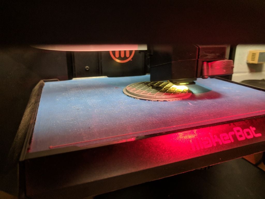
我開始為3英寸電纜卷筒打印三維部件,電纜卷筒位于電機軸上。我用鋼板切割了兩個5英寸的圓盤,并在鉆孔后將它們安裝在兩側。 3d打印的鼓。我焊接了一個底盤,用一個1英寸的箱形鋼管將電機擰緊。裝配好電纜卷筒并將絞盤安裝到底盤后,我準備從硬件上移開。
第3步:軟件


編碼經過多次測試迭代,找出最佳方法無線控制。一個版本有一個旋鈕控制速度和方向與GO按鈕。這非常方便動態調整,但不可重復。
代碼的最終版本設計可編程根據命令執行的提示。對于這個版本,只有兩個提示可供選擇,這些提示在Arduino軟件中編程。那些在他們的工具包中有超過3個按鈕的人可以輕松擴展功能。選擇提示加載將信息輸入當前提示,然后按住GO按鈕命令電機移動。釋放按鈕自動y停止電機,作為一種死人開關。最后,作為一種緊急停止,通過翻轉電源板上的開關或從墻上拔下電源來切斷電機電源,將使制動器停止并停止電機。
我的發射器代碼嵌入在下面。
/* Transmitter Code
* Code to store a cue and transmit it with a RF24L01+ to a receiver
* Credit to Mark Hughes for sharing his remote control project that
* helped me understand and debug my nRF24L01 setup
*
* This is the code for the transmitter portion for my winch project.
* It consists of 2 buttons, each with cue information, and a third button
* which is the “GO” button. Pressing and holding the button transmits to
* the receiver the information for the motor controller.
*
* Hook Up from nRF24L01
* Gnd to GND
* VCC to VCC
* CE to Digital 9
* CSN to Digital 10
* SCK to Digital 13
* MOSI to Digital 11
* MISO to Digital 12
* IRQ to Digital 8
*/
#include SPI.h
#include RF24.h
// Radio Configuration
RF24 radio(9,10);
byte addresses[][6] = {“1Node”,“2Node”};
bool radioNumber=1;
bool role = 1; //Control transmit 1/receive 0
//hardware attachments
const int GoButton = 4; //hold button to run loaded cue
const int Cue1 = 3; //press button to load cue
const int Cue2 = 2; //press button to load cue
const int ledPin = LED_BUILTIN; //LED flashes for debug purposes
//variables
int GoButtonState = 0;
int Cue1State = 0;
int Cue2State = 0;
int MotorSpeed = 0;
int STOP = 0; //for deadman switch. Constant broadcast a 0 speed to winch for safety
void setup() {
// put your setup code here, to run once:
pinMode (ledPin, OUTPUT);
pinMode (GoButton, INPUT);
pinMode (Cue1, INPUT);
pinMode (Cue2, INPUT);
Serial.begin(9600); // Get ready to send data back for debugging purposes
radio.begin(); // Get the transmitter ready
radio.setPALevel(RF24_PA_LOW); // Set the power to low
radio.openWritingPipe(addresses[1]); // Where we send data out
radio.openReadingPipe(1,addresses[0]);// Where we receive data back
}
void loop() {
// put your main code here, to run repeatedly:
GoButtonState = digitalRead(GoButton);
Cue1State = digitalRead(Cue1);
Cue2State = digitalRead(Cue2);
// Serial.print(ForeAft_Output);
radio.stopListening(); // Stop listening and begin transmitting
delay(50); // make delay longer for debugging
while (digitalRead(GoButton) == HIGH) {
SendMotorSignal(); //subroutine for broadcast
}
if (Cue1State == HIGH) {
MotorSpeed = -127; //speed for Cue1. Input can be from -127 to 127
digitalWrite(ledPin,HIGH); //LED flashing is helpful for debug
delay(100);
digitalWrite(ledPin, LOW);
delay(200);
}
if (Cue2State == HIGH) {
MotorSpeed = 127; //speed for Cue2. Input can be from -127 to 127
digitalWrite(ledPin, HIGH); //LED flashing is helpful for debug
delay(200);
digitalWrite(ledPin, LOW);
delay(100);
}
else {
digitalWrite(ledPin, LOW);
radio.stopListening(); // Stop listening and begin transmitting
delay(50); // make delay longer for debugging
if(radio.write(&STOP, sizeof(STOP)),Serial.println(“sent STOP”)); //Deadman switch function. Sends value of 0
radio.startListening();
//delay(50); //make delay longer for debugging
}
}
//subroutine for sending signal to motor
void SendMotorSignal() {
radio.stopListening();
delay(50); //make delay longer for debugging
if(radio.write(&MotorSpeed, sizeof(MotorSpeed)), Serial.println(“sent MotorSpeed”),(MotorSpeed));
digitalWrite(ledPin,HIGH); //LED helpful for debug
delay(100);
digitalWrite(ledPin, LOW);
delay(50);
}
對于接收器。
/* Receiver Code
* Code to receive data from RF24L01+ and use it to control a motor
* Thanks to Mark Hughes for sharing his remote control project that was
* incredibly valuable to me for learning how to make the radio library function.
*
* This is the code for the receiver portion for my winch project. It listens
* for the motor speed information to be transmitted, then sends it to the SyRen
* motor controller using a simplified serial packet.
*
* The receiver is using Software Serial to have the communication line to the SyRen
* on Pin 3, primarily so that the Arduino can be plugged into the computer
* during development.
*
* Hook Up from nRF24L01
* Gnd to GND
* VCC to VCC
* CE to Digital 9
* CSN to Digital 10
* SCK to Digital 13
* MOSI to Digital 11
* MISO to Digital 12
* IRQ to Digital 8
* */
#include SoftwareSerial.h //for serial communication on a designated pin
#include SyRenSimplified.h //library for SyRen
#include SPI.h
#include RF24.h
//SyRen Config
SoftwareSerial SWSerial(NOT_A_PIN, 3); // RX on no pin (unused), TX on pin 3 (to S1)。
SyRenSimplified SR(SWSerial); // Use SWSerial as the serial port.
//Radio Configuration
bool radioNumber=0;
RF24 radio(9,10);
byte addresses[][6] = {“1Node”,“2Node”};
bool role = 0; //Control transmit/receive
// Create variables to control servo value
unsigned int MotorSpeed; // Expected range -127 to 127
void setup() {
Serial.begin(9600); // Get ready to send data back for debugging purposes
SWSerial.begin(9600); // for communication to SyRen
radio.begin(); // Initialize radio
radio.setPALevel(RF24_PA_LOW); // Set the power output to low
radio.openWritingPipe(addresses[0]);
radio.openReadingPipe(1,addresses[1]);
radio.startListening();
}
void loop() {
delay(50); //increase for debuggy, decrease to decrease jitter
if(radio.available()){
radio.read(&MotorSpeed,sizeof(MotorSpeed));
}
else {Serial.print(“No radio”);
}
//Serial.print(MotorSpeed); //for debug purposes
//Serial.print(“ ”);
//delay(100);
//delay can be helpful when debugging- can be finetuned, but no delay causes
//glitches to happen in serial monitor. I think there may be conflict
//between SWSerial to the Syren and nRF and USB serial.
SR.motor(MotorSpeed); // Command the motor to move or, where the magic happens
}
這就是編碼!
第4步:全面測試


這里有一些視頻,我正在測試車間的絞車,以及一些額外的組件圖片。
一些想法 -
底盤設計為可以以不同方向安裝,并且可以輕松添加C形夾,奶酪架或直接安裝在地板或甲板上。通過無線設置,絞車僅需120伏電源即可與其接收器一起工作。變送器只是一個獨立的電源,因此也需要一個插座插入。
速度 -
我在這兩個方向上的速度都是每秒2英尺左右以最快的速度運行,這是一個非常好的速度,并且與JR Clancy Powerlift系統的速度相匹配。
容量 -
絞盤將保持10磅。它可能會持有更多,但到目前為止,我已經把它增加了10磅。如果不對系統進行破壞性測試,很難猜出故障點是什么。電纜是1/16“英寸的飛機電纜,斷裂強度為480磅。我不知道這是否會先失效,或者電機上的軸是否會斷裂,或者三維印刷滾筒是否會破碎或撕裂。
然而,對于10-20磅范圍內的物體,我認為這種絞盤將完美運作。
擴張 -
我有一些元素我還在努力。有一個編碼器和袋鼠板等待麻煩并重新安裝在系統上,但我很難讓編碼器和袋鼠接受對方運行強制調整周期。一旦到位,絞車將具有可編程定位功能。另一個需要的項目是行程頂部的限位開關,以防止有效載荷撞入絞盤。
-
絞車
+關注
關注
0文章
5瀏覽量
6816
發布評論請先 登錄
相關推薦
松下MPS媒體制作平臺概述
虛擬制作技術在廣告領域中的應用與挑戰
HDI板盲孔制作常見缺陷及解決
AIGC在視頻內容制作中的應用前景
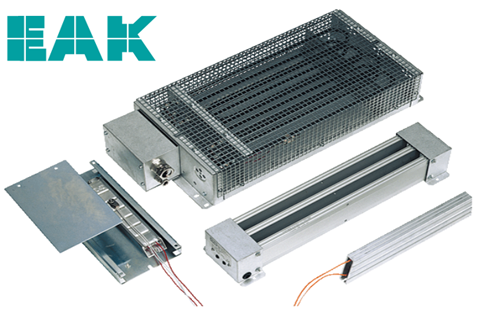
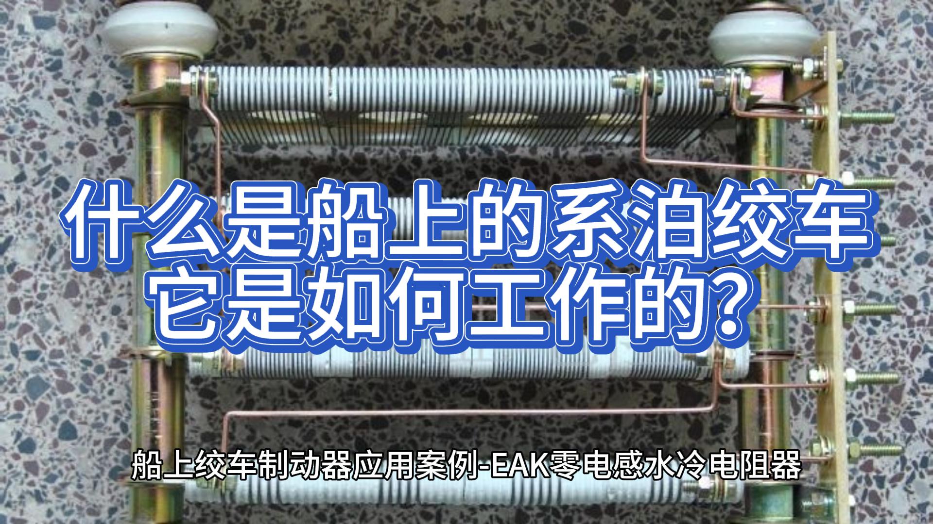
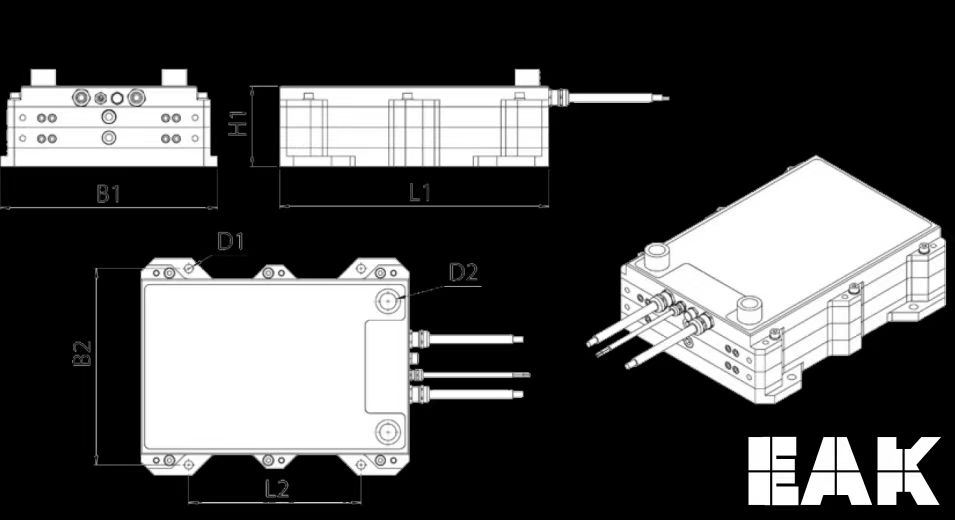
零電感水冷電阻器用于船舶,甲板機械的絞車,降低錨和起重機
光刻掩膜版制作流程
PCB電路板設計與制作的步驟和要點
電阻柜的電阻元件如何制作?


 工商網監
工商網監
評論